Course Assignment Description:
“This lab is an introduction to the Arduino, its Integrated Development Environment (IDE), and digital I/O on the Arduino. We will set up the workflow of programming an Arduino and learn about how to manipulate and sense its digital pins. Over a series of steps, we will build an LED reaction game to test who has the fastest reflexes!”
Link to GIThub Gist for code: https://gist.github.com/jafo3802/35b888d3c3b4148d9bc98d576f4bd6eb
Materials:
- Arduino (Elegoo) Uno R3 Controller Board
- USB Cable
- USB Adapter (if you have a USB-C-only laptop)
- Button
- 830 Tie-Points Breadboard
- Breadboard Jumper Wire
- Resistors
- LEDs
- Multimeter
Part 1: Setting up the Arduino
For the initial setup of the Arduino, I connected the Arduino UNO to the USB barrel jack, and then connected the USB to my computer. On my laptop, I opened the Arduino IDE where there are example code available to run the Arduino. Using the “Blink” example, the code connects to the Arduino to turn the light on the board on and off in 1 second intervals. (example code
/*
  This example code is in the public domain.

  https://www.arduino.cc/en/Tutorial/BuiltInExamples/Blink
*/

// the setup function runs once when you press reset or power the board

void setup() {
  // initialize digital pin LED_BUILTIN as an output.
  pinMode(LED_BUILTIN, OUTPUT);
}

// the loop function runs over and over again forever
void loop() {
  digitalWrite(LED_BUILTIN, HIGH);  // turn the LED on (HIGH is the voltage level)
  delay(1000);                      // wait for a second
  digitalWrite(LED_BUILTIN, LOW);   // turn the LED off by making the voltage LOW
  delay(1000);                      // wait for a second
}
Part 2: Blinking an external LED
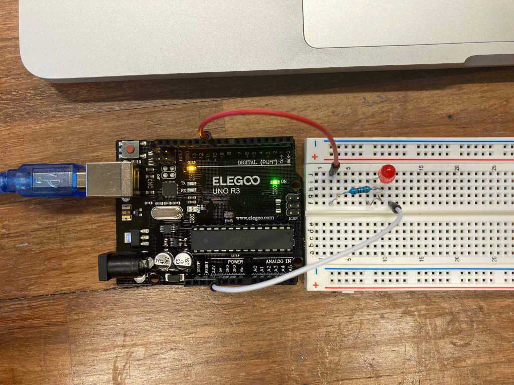
For the next part of the lab, I extended the blinking LED light to power an individual LED connect to a breadboard. a simple circuit running the power to a 100 Ohm resistor, then through the red LED, and then back to the pin in the Arduino to control the LED. Using the digitalWrite() and delay() functions, I made the light turn on and off for a duration of 1 second (or 1000 milliseconds) within the loop() to control the LED.
In the above video, the LED light turns on for 1 second and turns off for 1 second.
In order to further my understanding of the Arduino code, I manipulated the code to change the speed at which the LED turns off and on. I did this by changing the delay(1000) function from 1000 milliseconds to 100 milliseconds, making the light blink at a much faster rate.
/*
  This example code is in the public domain.

  https://www.arduino.cc/en/Tutorial/BuiltInExamples/Blink
*/

// the setup function runs once when you press reset or power the board

int LED_PIN = 10;

void setup() {
  // initialize digital pin LED_BUILTIN as an output.
  pinMode(LED_PIN, OUTPUT);
}

// the loop function runs over and over again forever
void loop() {
  digitalWrite(LED_PIN, HIGH);  // turn the LED on (HIGH is the voltage level)
  delay(1000);                  // wait for a second
  digitalWrite(LED_PIN, LOW);   // turn the LED off by making the voltage LOW
  delay(1000);                  // wait for a second
}
Part 3: Button Press and Serial Monitor
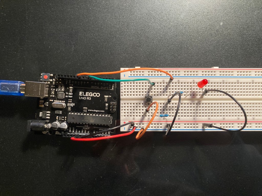
The next part of the lab required a button switch to be added to the LED light set up. Rather than a simple circuit in series, the LED and button switch are now set up in a parallel circuit to create a pull-down resistor to divert the 5V power between lighting up the LED and grounding the circuit when button is not being pushed.
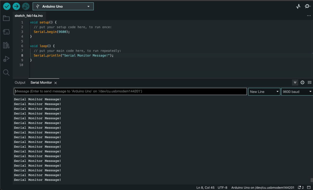
Now that I have a working button and LED circuit, it’s time to work on the software side of the lab to control the Arduino. To understand what is happening in the code, I used the Serial Monitor in the Arduino sketch code to get an output for what is going on within the code. For starters, I created a simple Serial.print() statement to output “Serial Monitor Message!” over a loop as the code ran to the control board.
For the final portion of Part 3 of this lab, I put my knowledge of Serial output software and the physical circuit together. I create a code (seen below) that reads in the input of the button connected to a control pin that Serial prints when the button is pressed. Using a while() loop, the algorithm runs within the loop while the button is not pressed. Once the button is pressed, the Serial Monitor outputs a check saying “pressed” and break out of the while() function and returns to the top of the loop() function, outputting the “Waiting for press” message and continuing the recursive code.
While testing this button press, there was some initial oscillation when the button was pressed. This could be caused by the physical button switch “bouncing” as my finger pushes it down, creating multiple high/low inputs until the button is fully pushed down. This can be avoided by “debouncing” the initial input by ignoring the first few milliseconds of the input and delaying the input read of the button push.
int INPUT_PIN = 7;
int LEDPIN = 10;
int buttonState = 0;

void setup() {
  // put your setup code here, to run once:
  pinMode(INPUT_PIN, INPUT);
  Serial.begin(9600);

}

void loop() {
  // put your main code here, to run repeatedly:
  int reading = digitalRead(INPUT_PIN);
  //resets the reading to LOW when not pushed
  if (reading == LOW){
    Serial.println("Waiting for press");
  }

  //while the button is off, run through this loop
  while(reading ==LOW){

    //changes the reading to HIGH when pushed
    reading = digitalRead(INPUT_PIN);

    // out message to indicate button push
    if(reading == HIGH){
      Serial.println("pressed");

    }
   //loop breaks when reading = HIGH
  }

}
Part 4: LED Reaction Game
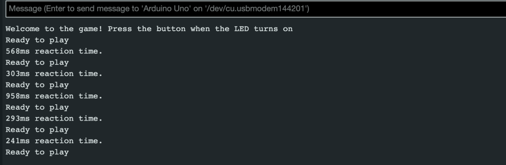
This final part of the lab was to create a reaction game, where the player presses the button as soon as the LED turns on after a random amount of time, then outputs the time it took (in milliseconds) to press the button, measuring the players reaction time.
Above is a video demonstrating the game in action. Once the code is compiled, the game welcomes the player and prints a “Ready to play” statement at the beginning of each round. Once the ready statement is printed, the LED will turn on between 0.5 seconds and 5 seconds. When the button is pushed, the time between the LED turning on and the button being pushed is printed and the next round begins. An example of the outputs can be seen below.
The code for the game can be seen below. It follows a simple loop that initiates the LED to turn on using a random number of milliseconds between 500 and 5000. In order to calculate the reaction time, the millis() function returns the time relative to when the loop starts plus the delay time. Once the light turns on, the while() loop waits for the player input for the button press, and breaks the loop when the reading is HIGH or “pressed” and turns of the LED.
int INPUT_PIN = 7;
int LEDPIN = 10;
int buttonState = 0;

//int ledState = HIGH;
//int lastButtonState = LOW;


void setup() {
  // put your setup code here, to run once:

  //initial input/output pins
  pinMode(INPUT_PIN, INPUT);
  pinMode(LEDPIN,OUTPUT);

  randomSeed(3); //for random number generator
  Serial.begin(9600);//Serial Monitor output initiation

  Serial.println("Welcome to the game! Press the button when the LED turns on"); //game start output

}

void loop() {
  // put your main code here, to run repeatedly:
  int buttonState = digitalRead(INPUT_PIN); //variable for button press
  int LEDcheck = digitalRead(LEDPIN); //variable for LED
  digitalWrite(LEDPIN,LOW); //set LED to off

  int currentTime = millis(); //variable to measure time between LED 'ON' and button press

  int randomNum = random(500,5000); //random start time variable
  Serial.println("Ready to play"); //start of game

  int time = millis() + randomNum; //current time + the delay in milliseconds

  delay(randomNum); //random delay for LED turning on
  digitalWrite(LEDPIN,HIGH); //turns LED on

  buttonState = digitalRead(INPUT_PIN); // sets reading for when the button is pressed.

  while(buttonState == LOW){
    buttonState = digitalRead(INPUT_PIN);//breaks loop when buttonState is HIGH
  }
  digitalWrite(LEDPIN, LOW); //turn off LED after press

  Serial.print(millis() - time); //output the current time minus the delay time to start the game
  Serial.println("ms reaction time."); //output reading of reaction time in milliseconds

  delay(2000); //delay 2 seconds between rounds

}
Conclusions
This lab was a challenge in learning to code in Arduino. The loop() function that runs the Arduino controller over and over makes it difficult to run the program and have it stop at certain parts of the code. This was solved by using a nested while() loop within the loop() function itself.
Once the loops were satisfied, creating game was easy until calculating the reaction time. I had to research how to use the millis() function to use instead of the delay() function to get an accurate measure of the time the passed between LED turning on and the button being pressed. Finding the correct calculation for the reaction time required my variables than I had first expected.
