Description:
“In this lab we will learn how to create interactive animations and visualizations on our computers using Processing, and then connect them to the Arduino to control them using electronics! We learn about Processing and how to use it, and how to set up serial communication between Processing and the Arduino. This is an open-ended lab to allow you to explore the depths of Processing and build something creative and exciting as a practice for your final project!”
Github Link for code: https://github.com/jafo3802/lab7-Serial-Communication
Materials:
- Arduino (Elegoo) Uno R3 Controller Board
- USB Cable
- USB Adapter (if you have a USB-C-only laptop)
- Breadboard Jumper Wire
- Joystick
- Multimeter
Part 0: Setting up Processing
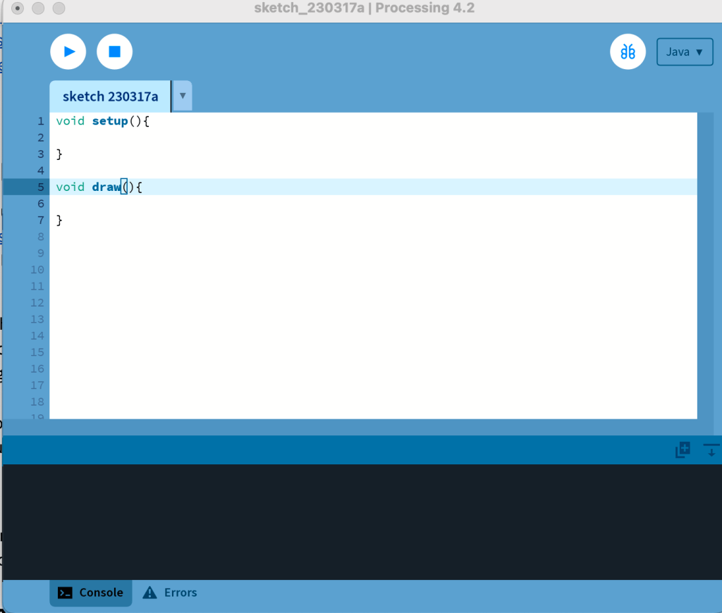
For this lab, I used Processing Development Environment to create serial communication between the Arduino and a computer processor. I downloaded the software from their website and opened up the IDE to begin writing code. The setup() and draw() functions are similar to the setup() and loop() functions in the Arduino IDE.
Part 1: Creating with Processing
To start using Processing, I made a simple environment that moved with the mouse cursor. Using the ellipse() function in Processing, I mapped the position of the mouse to create a circle wherever the cursor moved using the mouseX and mouseY commands. The code snippet used in Processing can be seen below the video of the sketch running.
void setup() {    // Executes once
  // Creates a window of size width 640, height 480
  size(640, 480);
}

void draw() {     // Executes in a constant loop
  fill(255);
  ellipse(mouseX, mouseY, 80, 80);
}
Next, I adjusted the above code to change the size of the ellipse and its color.
void setup() {    // Executes once
  // Creates a window of size width 640, height 480
  size(640, 480);
}

void draw() {     // Executes in a constant loop
  fill(270, 90, 5);
  ellipse(mouseX, mouseY, 100, 125);
}
Part 2: Processing with Arduino
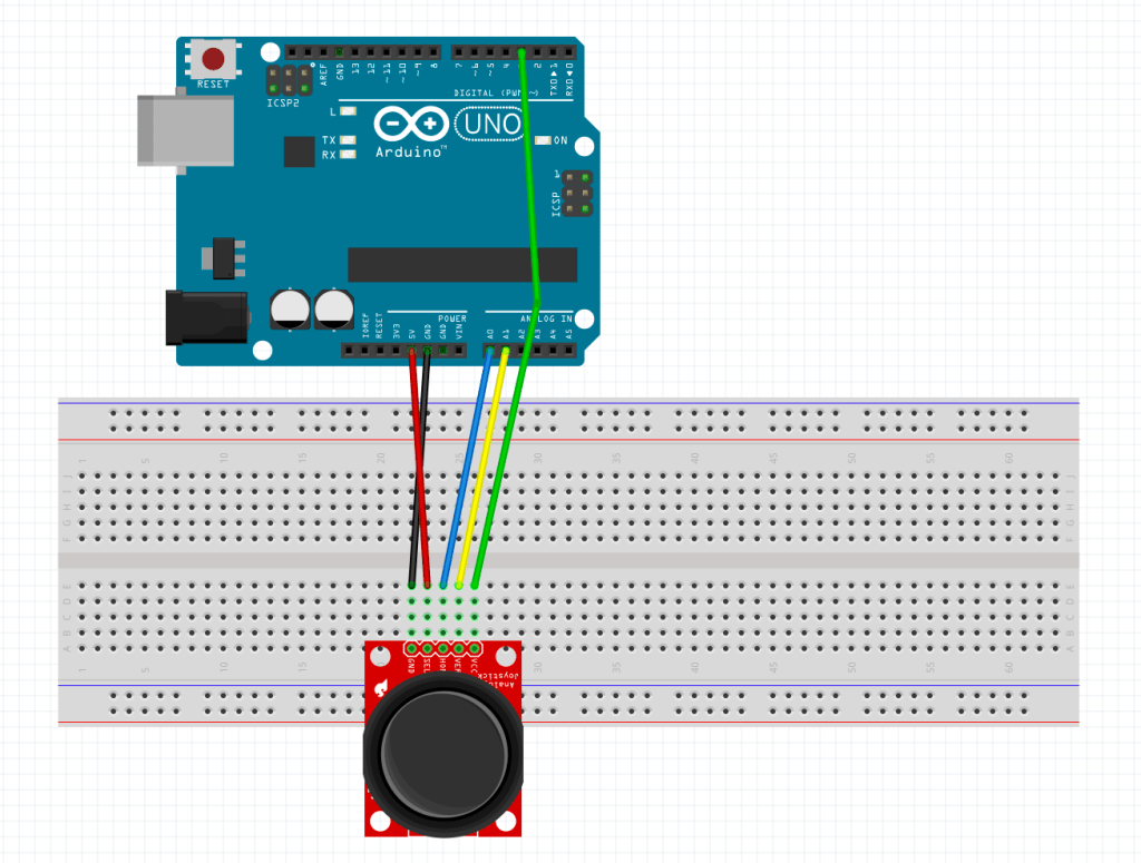
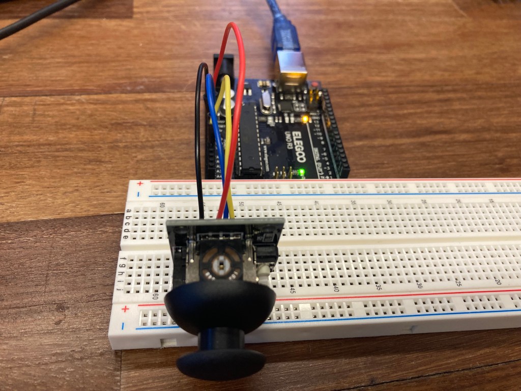
For this part of the lab, I created a serial communication between the Arduino hardware and the Processing environment. This works by using the Arduino code’s Serial.print() function to send statements to the Processing application that converts those messages to be used within its digital monitor. Using the Joystick connected to the Arduino controller, I created a sketch that would serial print the X and Y coordinates of the Joystick along with the digital button press of the stick. A demonstration and code snippet can be seen below.
The Serial communication is sent in the form of long string denoted by and end-line character with “;” and “:” delimiters between segments of information (example: “xVal:435;yVal:957;swVal:0”). We were provided Processing code that would parse this data using a key value pair library to easily access this data once it was read into Processing.
The Serial communication is sent in the form
Arduino Code:
const int xPin = A0;
const int yPin = A1;
const int swPin = 2;

void setup()
{
  pinMode(xPin, INPUT);
  pinMode(yPin, INPUT);
  pinMode(swPin, INPUT_PULLUP);
  Serial.begin(9600);
}

void loop()
{

  int x = analogRead(xPin);
  int y = analogRead(yPin);
  int sw = digitalRead(swPin);

  //Serial.print("xVal:435;yVal:957;swVal:0");
  Serial.print("xVal:");
  Serial.print(x);
  Serial.print(";yVal:");
  Serial.print(y);
  Serial.print(";swVal:");
  Serial.println(sw);
}
Processing Code:
import processing.serial.*;    // Importing the Serial library
import java.util.Map;          // Importing library to use HashMap

Serial port;    // Creating an object to handle serial communication

// String variable to store the received serial string
String serialString;
// Dictionary for all the values received over serial
HashMap<String, Integer> serialData = new HashMap<String, Integer>();

void setup() {    // Executes once
  size(640, 480);

  // Specifying the USB port to which the Arduino is connected
  // And attaching to the serial object

  // ##### CHANGE FOR YOUR MACHINE, CHECK IN ARDUINO IDE #####
  String portName = "/dev/cu.usbmodem143201";

  port = new Serial(this, portName, 9600);
  port.bufferUntil('\n');
}

void draw() {
  // Parse the data received over Serial in the form
  // key1:value1;key2:value2;key3:value3...
  parseSerialData();

  // Checks if serialData is available and updated before using it
  if (!serialData.isEmpty()) {

    //################# WRITE YOUR CODE HERE #####################//
    int x = serialData.get("xVal");
    int y = serialData.get("yVal");
    int button = serialData.get("swVal");

    x = int(map(x, 0, 1023, 0, 640));
    y = int(map(y, 0, 1023, 0, 480));

    mouseX = x;
    mouseY = y;

    if(button == 0){
      fill(0);
      ellipse(x, y, 80, 80);
    }else{
      fill(255, 90, 5);
      ellipse(x, y, 80, 80);
    }
  }
}

// serialEvent function
  // Triggered whenever data is received over serial
void serialEvent(Serial p) {
  serialString = p.readString();
}

// parseSerialData function
  // Read the serialString variable of the form
  // "Key1:Value1;Key2:Value2;Key3:Value3 ..."
  // And update the serialData HashMap
void parseSerialData() {
  // Delimiters used to split the string
  final String MAP_ITEMS_DELIMITER = ";";  // ; to split key-value pairs
  final String KEY_VALUE_DELIMITER = ":";  // : to split key and value

  if (serialString == null || serialString.length() == 0) {
    // Do nothing if empty string
    return;
  }

  String[] keyValuePairStrings = serialString.split(MAP_ITEMS_DELIMITER);

  for (String kvString : keyValuePairStrings) {
    String[] keyValuePair = kvString.split(KEY_VALUE_DELIMITER);
    if (keyValuePair == null || keyValuePair.length < 2) {
      // skip if we have bad input
      continue;
    }

    // trim our values now
    String keyItem = trim(keyValuePair[0]);
    String value = trim(keyValuePair[1]);
    int itemValue = int(value);

    // Put the value into our hashmap
    serialData.put(keyItem, itemValue);
  }
}
Part 3: Creating My Own Visualization
For the final part of this lab, it required us to crate my own visualization using the Processing library. I used two push buttons along with the joystick for the electronic inputs and three LED’s (red, green, blue) as electronic outputs. The Visualization would work similar to the previous parts that would move a circle according to the position of the joystick. When the left button is pushed, it would change the color of the circle to blue and the blue LED would light up. The right button would do the same but change the circle color to red and the red LED would light up. Finally, pushing the joystick in would change the circle to green and light up the green LED.
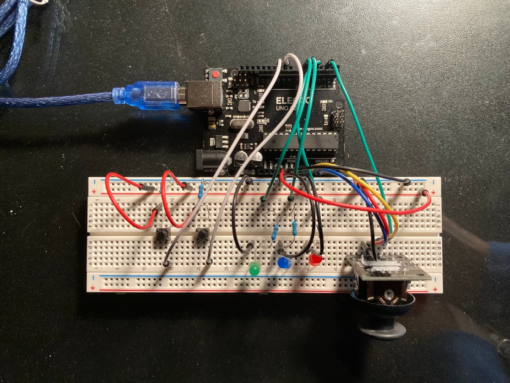
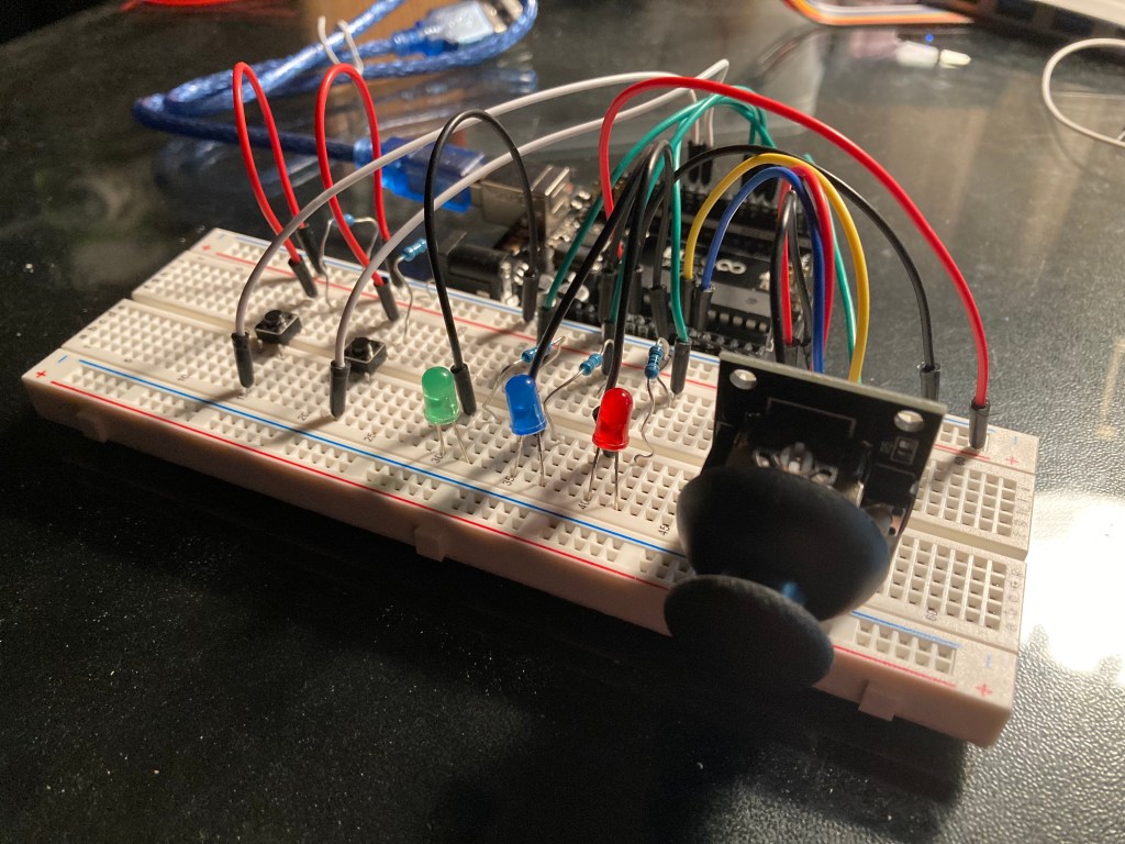
A demonstration of the LED’s lighting up depending on if the left, right, or joystick button is pushed.
A demonstration of the Processing code working with the Arduino hardware.
Arduino Code:
const int xPin = A0;
const int yPin = A1;
const int swPin = 2;

const int button1 = 10;
const int button2 = 9;

const int rLED = 4;
const int bLED = 5;
const int gLED = 6;

void setup()
{
  pinMode(xPin, INPUT);
  pinMode(yPin, INPUT);
  pinMode(swPin, INPUT_PULLUP);

  pinMode(button1, INPUT);
  pinMode(button2, INPUT);

  pinMode(rLED, OUTPUT);
  pinMode(bLED, OUTPUT);
  pinMode(gLED, OUTPUT);

  Serial.begin(9600);
}

void loop()
{

  int x = analogRead(xPin);
  int y = analogRead(yPin);
  int sw = digitalRead(swPin);

  int b1 = digitalRead(button1);
  int b2 = digitalRead(button2);

    digitalWrite(gLED, LOW);
    digitalWrite(rLED, LOW);
    digitalWrite(bLED, LOW);

  if(sw == LOW){
    digitalWrite(gLED, HIGH);
  }
  if(b1 == HIGH){
    digitalWrite(bLED, HIGH);
  }
  if(b2 == HIGH){
    digitalWrite(rLED, HIGH);
  }
//Serial.print("b1:1;b2:0;xVal:435;yVal:957;swVal:0");

  Serial.print("xVal:");
  Serial.print(x);
  Serial.print(";yVal:");
  Serial.print(y);
  Serial.print(";swVal:");
  Serial.print(sw);
  Serial.print(";b1:");
  Serial.print(b1);
  Serial.print(";b2:");
  Serial.println(b2);
}
Processing Code:
import processing.serial.*;    // Importing the Serial library
import java.util.Map;          // Importing library to use HashMap

Serial port;    // Creating an object to handle serial communication

// String variable to store the received serial string
String serialString;
// Dictionary for all the values received over serial
HashMap<String, Integer> serialData = new HashMap<String, Integer>();

void setup() {    // Executes once
  size(640, 480);

  // Specifying the USB port to which the Arduino is connected
  // And attaching to the serial object

  // ##### CHANGE FOR YOUR MACHINE, CHECK IN ARDUINO IDE #####
  String portName = "/dev/cu.usbmodem143201";

  port = new Serial(this, portName, 9600);
  port.bufferUntil('\n');
}

void draw() {
  // Parse the data received over Serial in the form
  // key1:value1;key2:value2;key3:value3...
  parseSerialData();

  // Checks if serialData is available and updated before using it
  if (!serialData.isEmpty()) {

    //################# WRITE YOUR CODE HERE #####################//
    int x = serialData.get("xVal");
    int y = serialData.get("yVal");
    int button = serialData.get("swVal");
    int press1 = serialData.get("b1");
    int press2 = serialData.get("b2");

    x = int(map(x, 0, 1023, 0, 640));
    y = int(map(y, 0, 1023, 0, 480));

    mouseX = x;
    mouseY = y;


    if(button == 0){
      fill(0,255,0);
      ellipse(x, y, 80, 80);
    }
    else if(press1 == 1){
      fill(0,0,255);
      ellipse(x, y, 80, 80);
    }
    else if(press2 == 1){
      fill(255,0,0);
      ellipse(x, y, 80, 80);
    }else{
      fill(255,255,255);
      ellipse(x, y, 80, 80);
    }
  }
}

// serialEvent function
  // Triggered whenever data is received over serial
void serialEvent(Serial p) {
  serialString = p.readString();
}

// parseSerialData function
  // Read the serialString variable of the form
  // "Key1:Value1;Key2:Value2;Key3:Value3 ..."
  // And update the serialData HashMap
void parseSerialData() {
  // Delimiters used to split the string
  final String MAP_ITEMS_DELIMITER = ";";  // ; to split key-value pairs
  final String KEY_VALUE_DELIMITER = ":";  // : to split key and value

  if (serialString == null || serialString.length() == 0) {
    // Do nothing if empty string
    return;
  }

  String[] keyValuePairStrings = serialString.split(MAP_ITEMS_DELIMITER);

  for (String kvString : keyValuePairStrings) {
    String[] keyValuePair = kvString.split(KEY_VALUE_DELIMITER);
    if (keyValuePair == null || keyValuePair.length < 2) {
      // skip if we have bad input
      continue;
    }

    // trim our values now
    String keyItem = trim(keyValuePair[0]);
    String value = trim(keyValuePair[1]);
    int itemValue = int(value);

    // Put the value into our hashmap
    serialData.put(keyItem, itemValue);
  }
}
Conclusion:
I enjoyed this lab and found Processing much easier to use than other serial connections such as p5 that I have used in the past. The library within Processing has so much potential for creating digital artworks with different shapes and colors combined with the animations.
The lab focused more on the programming side of Arduino and Processing given that this is a serial communication lab, which I enjoyed doing more of rather than the hardware side of things. The last part of the lab was a little tricky when it came to adding all the electronic components onto the bread board. I found the wires getting crossed a few times when setting up the input buttons and LED outputs, but managed to get them organized in the end.
