Description:
“In this lab, we will be working with motors! Most of you have probably experienced motors in some form, whether it is the motor in your table fan, or in your RC car or drone. Motors come in different flavors, and we will be working with two types of motors in your kit for this lab – the servo motor and the DC motor. We will be connecting these to our Arduino boards in different ways and controlling them using the potentiometer and the joystick, and finally make an oscillating toy fan.”
Github link for code: https://github.com/jafo3802/Analog-Out
Materials:
- Arduino (Elegoo) Uno R3 Controller Board
- USB Cable
- USB Adapter (if you have a USB-C-only laptop)
- Breadboard Jumper Wire
- Resistors
- Power Supply Module
- Servo Motor SG90
- DC Motor and Fan Blade
- L293D IC
- Button
- Potentiometer
- 9V Battery with Snap-on Connector
- Multimeter
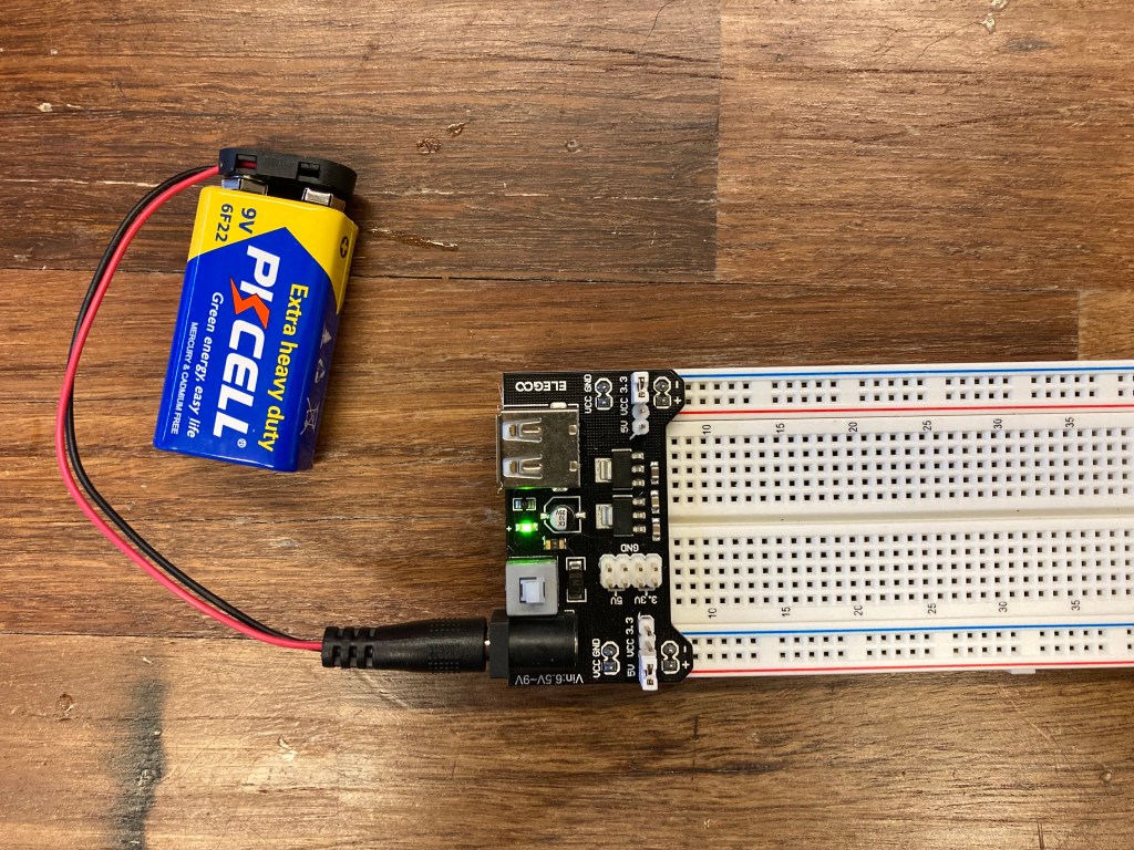
Part 0: Setting up Power
To begin, I had a refresher on how to set up the Power Module. Since the DC Motor requires more power than the than just 5V, I connected the power module to a 9V battery that would allow more power to operate the fan.
Part 1: Wiring the Servo
Next was to connect the Servo Motor to the breadboard. Using the power supplied from the 9V battery, the servo could have sufficient power to move through the power wire (red). Then the Arduino module connected to the signal wire (orange) would allow control over the servo movement. Finally, I needed to connect the servo ground wire (brown) to share a common ground with the Arduino ground through the negative rail on the end of the breadboard.

Pins 3, 5, 6, 9, 10, and 11 along with the A0 and A1 pins on the Arduino microcontroller allow Pulse-Width Modulation signals to be sent to an analog output.

To use the Servo, Arduino provides a free library with commands to control the Servo. So, I installed the Servo library by Michael Margolis with and included the file at the top of the .ino file to use these commands. Below is a demonstration of the Servo moving 180 degrees back and forth.
#include <Servo.h>

Servo servoA;  // create servo object to control a servo

int pos = 0;    // variable to store the servo position

void setup() {
  servoA.attach(9);  // attaches servo connected to Arduino pin 9 to the myservo object
  // Change pin # depending on where your servo is connected
}

void loop() {
  for (pos = 0; pos <= 180; pos += 1) { // goes from 0 to 180 in steps of 1 degree
    servoA.write(pos);              // tell servo to go to position in variable 'pos'
    delay(15);                       // waits 15ms for the servo to reach the position
  }
  for (pos = 180; pos >= 0; pos -= 1) { // goes from 180 degrees to 0 degrees
    servoA.write(pos);              // tell servo to go to position in variable 'pos'
    delay(15);                       // waits 15ms for the servo to reach the position
  }
}
Part 2: Controlling the Servo

For part 2, I added a potentiometer to the breadboard that would work in tandem with Servo. The power and ground are connected to the 5V pin and GND pin on the Arduino controller. The analog input wire connects back to the A0 pin on the Arduino to get the analog input as the potentiometer turns.
#include <Servo.h>

Servo servoA;  // create servo object to control a servo

int pos = 0;    // variable to store the servo position
int pot = A0;

void setup() {
  servoA.attach(9);  // attaches servo connected to Arduino pin 9 to the myservo object
  pinMode(pot,INPUT);
  Serial.begin(9600);
}

void loop() {
  int turn = analogRead(pot);
  turn = map(turn, 0, 1023, 0, 180);
  delay(15);
  servoA.write(turn);              // tell servo to go to position in variable 'pos'

}
Now that the potentiometer moves along with the Servo, I changed the delay in the Arduino sketch to a larger 50ms delay so that the Servo would move slower as the potentiometer moved
#include <Servo.h>
Servo servoA; // create servo object to control a servo
int pos = 0; // variable to store the servo position
int pot = A0;
void setup() {
servoA.attach(9); // attaches servo connected to Arduino pin 9 to the myservo object
pinMode(pot,INPUT);
Serial.begin(9600);
}
void loop() {
int turn = analogRead(pot);
turn = map(turn, 0, 1023, 0, 180);
delay(50);
servoA.write(turn); // tell servo to go to position in variable 'pos'
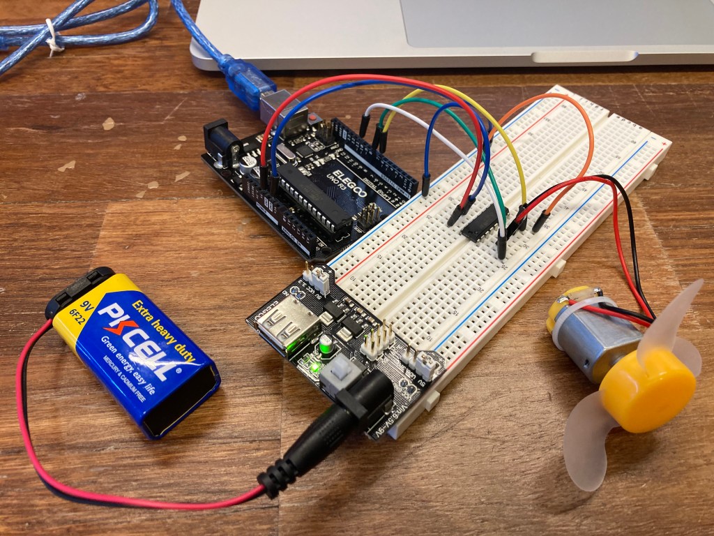
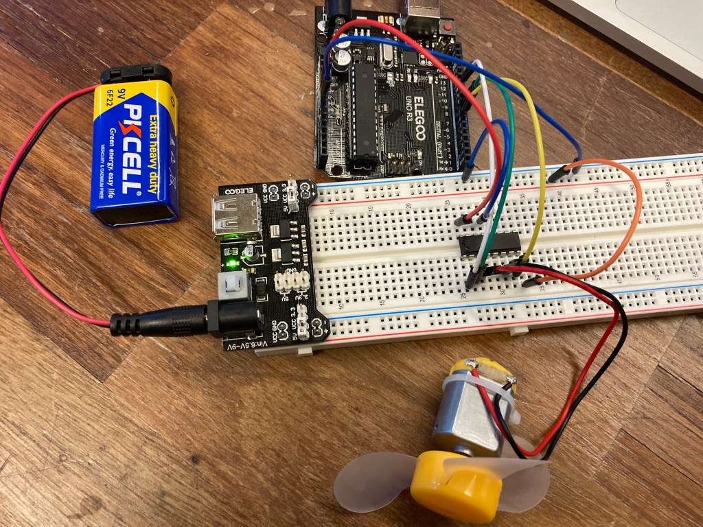
}Part 3: DC Motor and Motor Driver
For part 3, I connected the DC motor to the breadboard by connecting the power and ground to the positive and negative rails. This powers the motor at its maximum power since there is only the 9V power connected through the 5V power rail of the Power Module.
Next, my goal was to have the fan be able to spin in both the “forward” and “backward” direction. Since the fan only has a single input for the power, changing the direction of the spin required an H-bridge connection that consists of the 4 switches. Opening two switches at a time in the correct order allows power to flow either forward or backward through the fan and change its spin direction. Our Arduino kits allowed us to utilize the L293D chip, which has these dual-channel motor drive and the proper switches to change the spin direction.
Below is a demonstration of the fan spinning in the forward direction for 2 seconds, pauses for 1 second, then spins backwards for 2 seconds. The code was provided except for the backwards() function, which I coded. The in1 and in2 variables are the analog switches that change in the H-bridge in order to send current in the reverse direction to change the spin direction.
// Motor connections
const int enA = 11;
const int in1 = 8;
const int in2 = 7;

void setup() {
    // Set all the pins as outputs
    pinMode(enA, OUTPUT);
    pinMode(in1, OUTPUT);
    pinMode(in2, OUTPUT);

    // Turn off the motor to start with
    digitalWrite(enA, LOW);
    digitalWrite(in1, LOW);
    digitalWrite(in2, LOW);
}

void loop() {
    // Move the motor in forward direction for 2 seconds
    forward();
    delay(2000);

    // Stop for 1 second
    stop();
    delay(1000);

    // Move the motor in the backward direction for 2 seconds
    backward();
    delay(2000);

    // Stop for 1 second
    stop();
    delay(1000);
}

void forward() {
    digitalWrite(in1, HIGH);
    digitalWrite(in2, LOW);

    digitalWrite(enA, HIGH);
}

void backward() {
    digitalWrite(in1, LOW);
    digitalWrite(in2, HIGH);

    digitalWrite(enA, HIGH);

}


void stop() {
    digitalWrite(enA, LOW);
    digitalWrite(in1, LOW);
    digitalWrite(in2, LOW);
}
For the second half of part 3, the fan needed to ramp up and ramp down in the spin rate. To do this, I used the same algorithm from part 1 that moved the Servo a up and down using a for() loop. Although it is hard to tell in the video, the fan speeds up and slows down at a slow rate than when power directly.
// Motor connections
const int enA = 11;
const int in1 = 8;
const int in2 = 7;
void setup() {
// Set all the pins as outputs
pinMode(enA, OUTPUT);
pinMode(in1, OUTPUT);
pinMode(in2, OUTPUT);
// Turn off the motor to start with
digitalWrite(enA, LOW);
digitalWrite(in1, LOW);
digitalWrite(in2, LOW);
}
void loop() {
rampUp();
delay(1000);
rampDown();
delay(1000);
}
void forward() {
digitalWrite(in1, HIGH);
digitalWrite(in2, LOW);
digitalWrite(enA, HIGH);
}
void backward() {
digitalWrite(in1, LOW);
digitalWrite(in2, HIGH);
digitalWrite(enA, HIGH);
}
void rampUp(){
for (int pos = 0; pos <= 255; pos += 5){ // goes from 0 to 180 in steps of 1 degree
digitalWrite(in1, HIGH);
digitalWrite(in2, LOW);
digitalWrite(enA, pos);
delay(15);
}
}
void rampDown(){
for (int pos = 255; pos >= 0; pos -= 5) { // goes from 180 degrees to 0 degrees
digitalWrite(in1, HIGH);
digitalWrite(in2, LOW);
digitalWrite(enA, pos);
delay(15);
}
void stop() {
digitalWrite(enA, LOW);
digitalWrite(in1, LOW);
digitalWrite(in2, LOW);
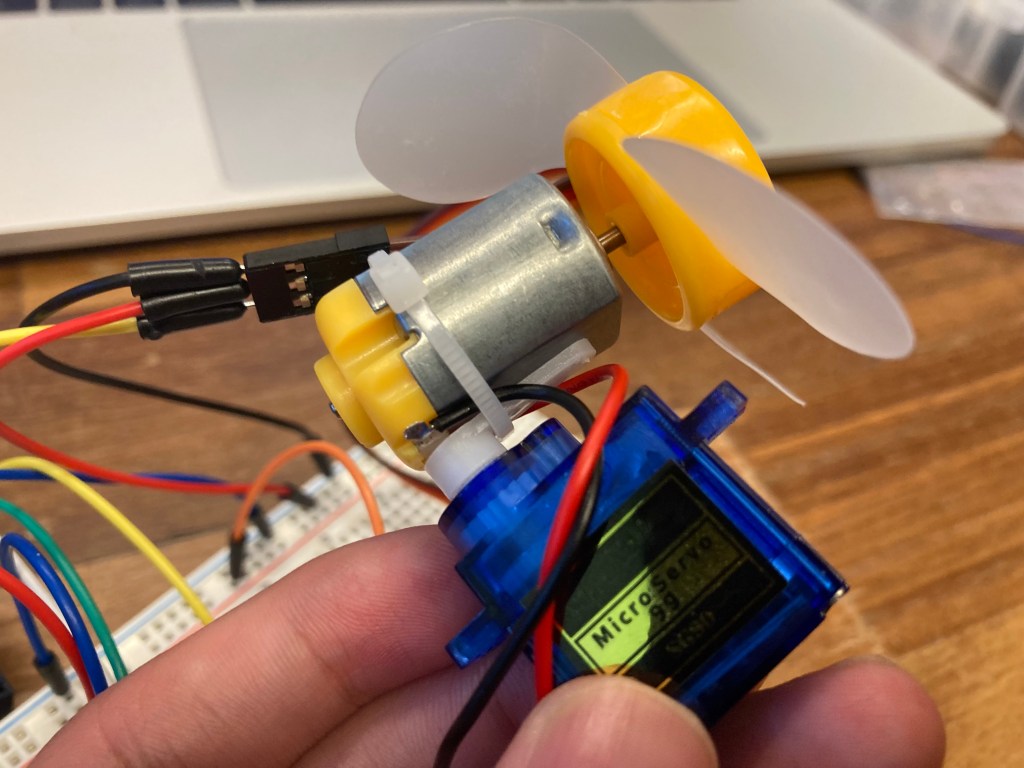
}Part 4: Table Top Fan
For the final part of this lab, I created a mini table top fan by combing the servo and DC motor fan. The servo would control the direction that the fan blows and the motor would spin at a desired rate that I chose.
The fan should work by moving the servo between 0 and 120 degree angles as the fan spun at 70% power. In order to have the fan spin at 70% speed, I used a PWM value of 179.
#include <Servo.h>

// Motor connections
const int enA = 11;
const int in1 = 8;
const int in2 = 7;


Servo servoA;  // create servo object to control a servo

int pos = 0;    // variable to store the servo position

void setup() {
  servoA.attach(A0);  // attaches servo connected to Arduino pin 9 to the myservo object
  // Change pin # depending on where your servo is connected
}

void loop() {

  forward();
  for (pos = 0; pos <= 120; pos += 1) { // goes from 0 to 180 in steps of 1 degree
    servoA.write(pos);              // tell servo to go to position in variable 'pos'
    delay(20);                       // waits 15ms for the servo to reach the position
  }
  for (pos = 120; pos >= 0; pos -= 1) { // goes from 180 degrees to 0 degrees
    servoA.write(pos);              // tell servo to go to position in variable 'pos'
    delay(20);                       // waits 15ms for the servo to reach the position
  }
}

void forward() {
    digitalWrite(in1, HIGH);
    digitalWrite(in2, LOW);

    digitalWrite(enA, 179);
}
Conclusion
I enjoyed this lab and its simplicity. Motors are a fairly basic analog output that does only one movement. I think the servo has more potential to manipulate due to the larger library of commands in the Arduino software.
