Lab Description
“In this lab, we begin interacting with electrical circuits in a more advanced fashion—using analog input! We will learn how to use our Arduino to take analog measurements from components like a potentiometer and an analog joystick, which is like a multi-dimensional potentiometer. We will use these inputs to control different LED arrangements and create a simple Whack-a-mole game that is then made more advanced in the Extra Volt!”
Materials:
- Arduino (Elegoo) Uno R3 Controller Board
- USB Cable
- USB Adapter (if you have a USB-C-only laptop)
- Breadboard Jumper Wire
- Resistors
- LEDs
- Potentiometer 10k
- Joystick Module
- Multimeter
Link to GitHub code: https://github.com/jafo3802/Whack-a-Mole
Part 1: Using a Potentiometer
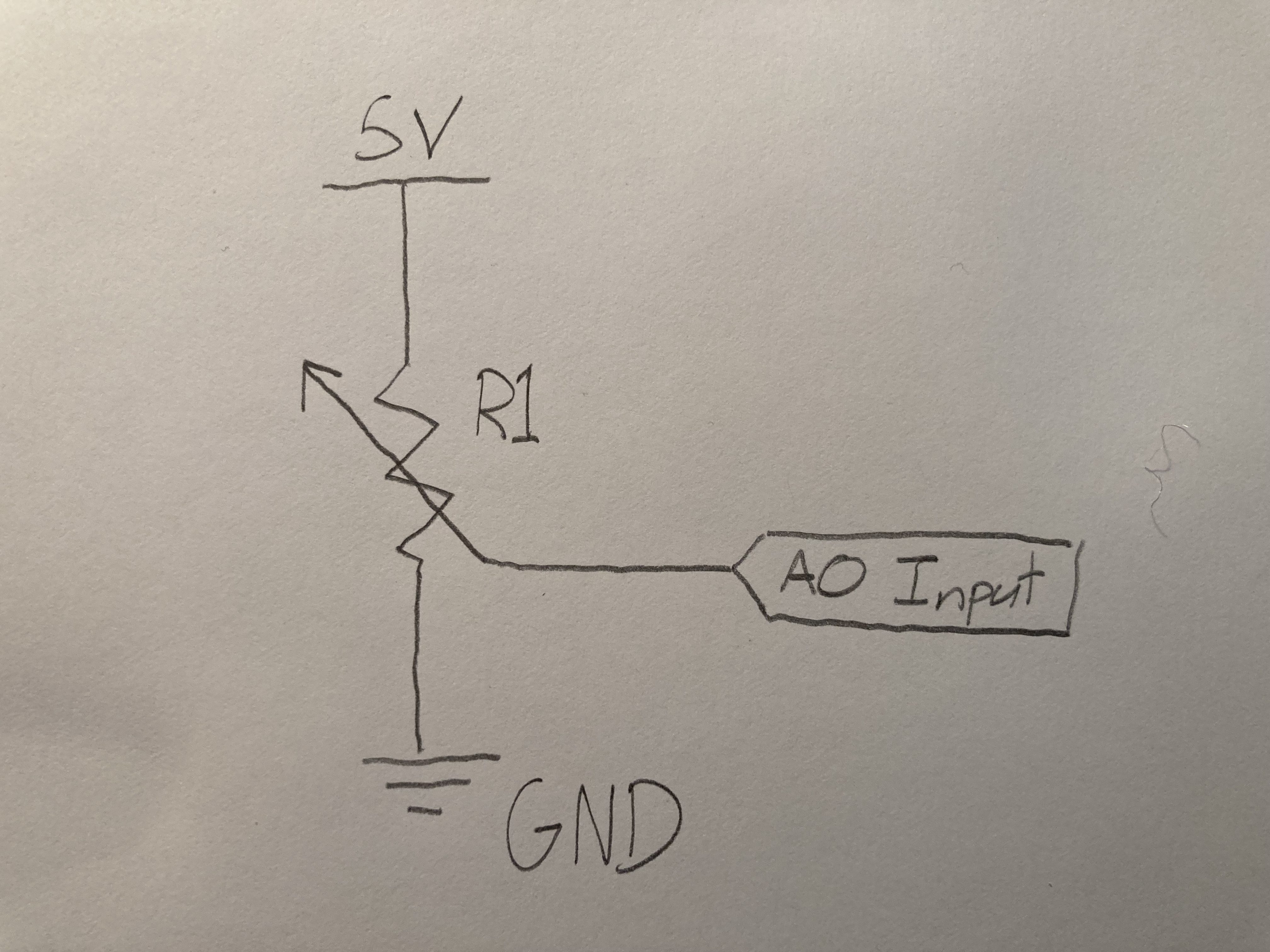
The first part of this lab had me set up a simple potentiometer connected to the Arduino microcontroller. The 5V power connects through the potentiometer which creates a variable resistance depending on how much the knob is turned. The input pin is connected to the A0 analog pin on the microcontroller which allows me to get the reading between 0-1023 to measure how much resistance is being applied to the current.
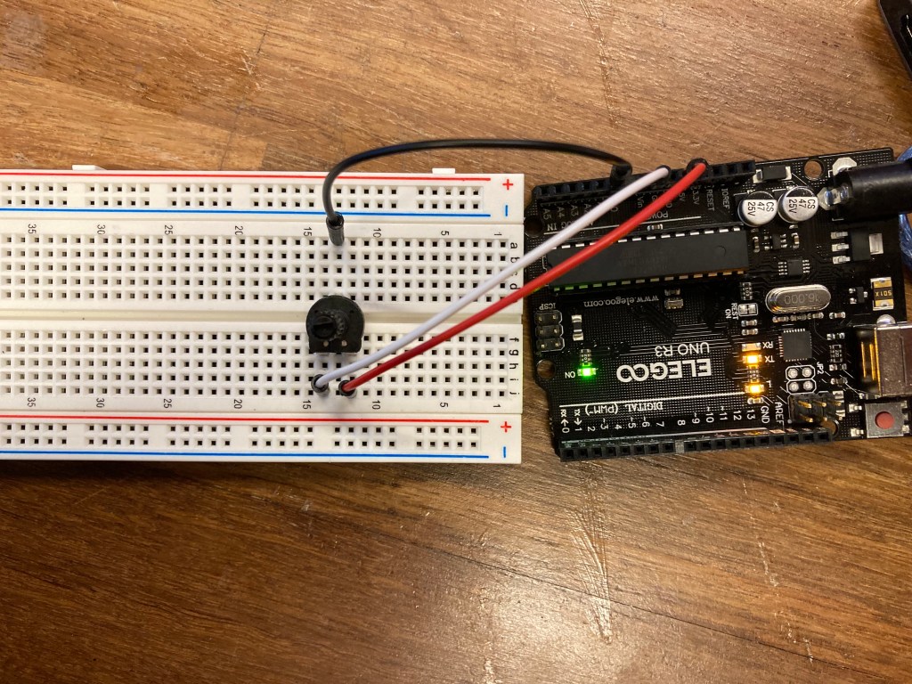
Below is a simple circuit diagram that shows the above circuit.
Using the analogRead() function in the Arduino library, I created a sketch that outputs the analog value as I turn the potentiometer. A demonstration and code framework can be seen below
const int POT_PIN = A0;

// the setup routine runs once when you press reset:
void setup() {
  // initialize serial communication at 9600 bits per second:
  Serial.begin(9600);
  pinMode(POT_PIN, INPUT);
}

// the loop routine runs over and over again forever:
void loop() {
  // read the input on analog pin 0:
  int sensorValue = analogRead(POT_PIN);


  // print out the value you read:
  Serial.println(sensorValue);


  delay(50);
}
Part 2: Potentiometer LED light up
Next, I set up a row of 5 LED lights to work with the potentiometer. The 5V power runs through the potentiometer first, and then connects down the positive side of the breadboard to connect to the 5 LED pins. I used 220 Ohm resistors to connect the LED back to the microcontroller. These LED’s are plugged into the digital pins 8-12 to control when they light up using the digitalWrite() function.
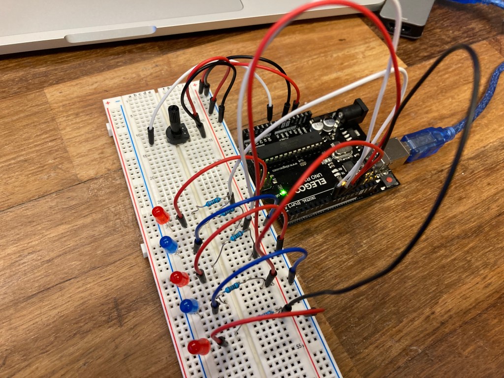
The circuit is meant to light up the LED’s as the potentiometer is turned, lighting one LED from left to right as less resistance is added while the knob turns. In order to convert the analog inputs to work within the desired range, I used the int y = map(x, x_min, x_max, y_min, y_max) function which converts the x variable into a range for the y variable. In this case, the x is the 0-1023 analog input range, and the y is the 0-5 digital input range to account for the 5 LED lights. A demonstration and example code can be seen below.
int pin_array[] = {8, 9, 10, 11, 12};
int sensorPin = A0;


void setup() {
  // put your setup code here, to run once:
  Serial.begin(9600);
  int pinMode(sensorPin,INPUT); //initialize pin for potentiometer
}

void loop() {
  // put your main code here, to run repeatedly:

  int sensorValue = analogRead(sensorPin); // read sensor value
  Serial.println(sensorValue);
  sensorValue = map(sensorValue, 0, 1023, 0, 5);

  if(sensorValue == 0){
    digitalWrite(pin_array[0],LOW);
    digitalWrite(pin_array[1],LOW);
    digitalWrite(pin_array[2],LOW);
    digitalWrite(pin_array[3],LOW);
    digitalWrite(pin_array[4],LOW);
  }else if(sensorValue == 1 ){
    digitalWrite(pin_array[0],HIGH);
    digitalWrite(pin_array[1],LOW);
    digitalWrite(pin_array[2],LOW);
    digitalWrite(pin_array[3],LOW);
    digitalWrite(pin_array[4],LOW);
  }else if(sensorValue == 2){
    digitalWrite(pin_array[0],HIGH);
    digitalWrite(pin_array[1],HIGH);
    digitalWrite(pin_array[2],LOW);
    digitalWrite(pin_array[3],LOW);
    digitalWrite(pin_array[4],LOW);
  }else if(sensorValue == 3){
    digitalWrite(pin_array[0],HIGH);
    digitalWrite(pin_array[1],HIGH);
    digitalWrite(pin_array[2],HIGH);
    digitalWrite(pin_array[3],LOW);
    digitalWrite(pin_array[4],LOW);
  }else if(sensorValue == 4){
    digitalWrite(pin_array[0],HIGH);
    digitalWrite(pin_array[1],HIGH);
    digitalWrite(pin_array[2],HIGH);
    digitalWrite(pin_array[3],HIGH);
    digitalWrite(pin_array[4],LOW);
  }else{
    digitalWrite(pin_array[0],HIGH);
    digitalWrite(pin_array[1],HIGH);
    digitalWrite(pin_array[2],HIGH);
    digitalWrite(pin_array[3],HIGH);
    digitalWrite(pin_array[4],HIGH);
  }
}
Part 3: Arduino Joystick
For part 3 of this lab, I set up a joystick in place of the knob potentiometer. a joystick works as two potentiometers that tracks the x and y direction that the joystick is pushed.
The joystick works from a 0-1023 analog input range for both the x and y direction. The values and corresponding coordinates are listed below. I included the map() values as well working within a range from 0-3. Normally, I would only need a range from 0-2 as there are 3 directions, but my joystick was a little loose and the 0-3 range worked better for what I needed to code in the next part.
- Center = x:500, y:521 // 1,1 (values after map() conversion )
- Up = x:1023, y:521 // 3,1
- Down = x:0, y:521 //0,1
- Left = x:500, y:0 // 1,0
- Right = x:500, y:1023 // 1,3
- Up-Left = x:1023, y:0 // 3,0
- Up-Right = x:1023, y:1023 // 3,3
- Down-Left = x:0, y:0 // 0,0
- Down-Right = x:0, y:1023 // 0,3
const int xPin = A0;
const int yPin = A1;

void setup() {
  // put your setup code here, to run once:
  Serial.begin(9600);
  pinMode(xPin,INPUT);
  pinMode(yPin,INPUT);

}

void loop() {
  // put your main code here, to run repeatedly:
  int xValue = analogRead(xPin);
  int yValue = analogRead(yPin);
  Serial.print("x: ");
  Serial.print(xValue);
  Serial.print(" y: ");
  Serial.println(yValue);

}
Part 4: LED lights with Joystick
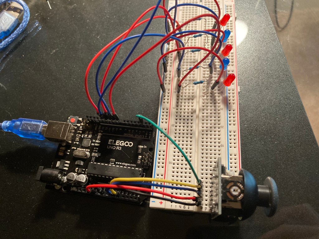
This part required the LED’s the light up in correspondence with the direction that the joystick moved. I set up 5 LED lights in a ‘+’ formation with 220 Ohm resistors leading back into the analog input pins of the microcontroller. When the stick was pushed up, the top light would light up, and if the stick was pushed diagonally down to the right, the bottom and right lights would light up.

Below is a demonstration of the working circuit along with the code that makes the LED and joystick work together.
const int xPin = A0;
const int yPin = A1;

const int center = 12;
const int up = 8;
const int left = 10;
const int right = 11;
const int down = 9;

void setup() {
  Serial.begin(9600);

  // set input and output pins
  pinMode(xPin,INPUT);
  pinMode(yPin,INPUT);

  pinMode(up, OUTPUT);
  pinMode(left, OUTPUT);
  pinMode(right, OUTPUT);
  pinMode(down, OUTPUT);
  pinMode(center, OUTPUT);

}

void loop() {
  //Read in joystick values for x and y direction
  int xValue = analogRead(xPin);
  int yValue = analogRead(yPin);

  //convert the analog input to number between 0-3
  int x = map(xValue, 0, 1023, 0, 3);
  int y = map(yValue, 0, 1023, 0, 3);

  //Print out the converted x and y positions
  Serial.print("x: ");
  Serial.print(x);
  Serial.print(" y: ");
  Serial.println(y);

  if(x == 1 && y == 1){ //Center position
    digitalWrite(center, HIGH);
    digitalWrite(up, LOW);
    digitalWrite(left, LOW);
    digitalWrite(right, LOW);
    digitalWrite(down, LOW);
  }else if(x == 3 && y == 1){ //Up position
    digitalWrite(center, LOW);
    digitalWrite(up, HIGH);
    digitalWrite(left, LOW);
    digitalWrite(right, LOW);
    digitalWrite(down, LOW);
  }else if(x == 0 && y == 1){//Down position
    digitalWrite(center, LOW);
    digitalWrite(up, LOW);
    digitalWrite(left, LOW);
    digitalWrite(right, LOW);
    digitalWrite(down, HIGH);
  }else if(x == 1 && y == 0){ //Left position
    digitalWrite(center, LOW);
    digitalWrite(up, LOW);
    digitalWrite(left, HIGH);
    digitalWrite(right, LOW);
    digitalWrite(down, LOW);
  }else if(x == 1 && y == 3){//Right Position
    digitalWrite(center, LOW);
    digitalWrite(up, LOW);
    digitalWrite(left, LOW);
    digitalWrite(right, HIGH);
    digitalWrite(down, LOW);
  }else if(x == 3 && y == 0){//Up-Left Position
    digitalWrite(center, LOW);
    digitalWrite(up, HIGH);
    digitalWrite(left, HIGH);
    digitalWrite(right, LOW);
    digitalWrite(down, LOW);
  }else if(x == 3 && y == 3){//Up-Right Position
    digitalWrite(center, LOW);
    digitalWrite(up, HIGH);
    digitalWrite(left, LOW);
    digitalWrite(right, HIGH);
    digitalWrite(down, LOW);
  }else if(x == 0 && y == 0){//Down-Left Position
    digitalWrite(center, LOW);
    digitalWrite(up, LOW);
    digitalWrite(left, HIGH);
    digitalWrite(right, LOW);
    digitalWrite(down, HIGH);
  }else if(x == 0 && y == 3){//Down-Right Position
    digitalWrite(center, LOW);
    digitalWrite(up, LOW);
    digitalWrite(left, LOW);
    digitalWrite(right, HIGH);
    digitalWrite(down, HIGH);
  }
}
Part 5: Basic LED Whack-A-Mole
For the final part of this lab, I created a ‘Whack-A-Mole’ type game where the user would have to move the joystick in the direction of the of the lit up LED. When the game begins, the center light would blink twice to indicate the start. Then a random light would light up in the up/down/right/left position 20 times for the user to play. At the end, a message in the Serial Monitor would output the time in seconds that it took to complete all 20 ‘whacks’.
//arduino pin variables
const int xPin = A0;
const int yPin = A1;
const int center = 12;
const int up = 8;
const int left = 10;
const int right = 11;
const int down = 9;

//values that correspond to the position of the joystick and lit LED
int upX = 3;
int upY = 1;
int downX = 0;
int downY = 1;
int leftX = 1;
int leftY = 0;
int rightX = 1;
int rightY = 3;

void setup() {
  Serial.begin(9600);

  // set input and output pins
  pinMode(xPin,INPUT);
  pinMode(yPin,INPUT);

  pinMode(up, OUTPUT);
  pinMode(left, OUTPUT);
  pinMode(right, OUTPUT);
  pinMode(down, OUTPUT);
  pinMode(center, OUTPUT);

  randomSeed(3);
}

void loop() {
  //start game with welcome message and 2 LED blinks
  Serial.println("Welcome to Whack-A-Mole! Move the joystick in the direction of the lit up LED.");
  digitalWrite(center,HIGH);
  delay(500);
  digitalWrite(center,LOW);
  delay(500);
  digitalWrite(center,HIGH);
  delay(500);
  digitalWrite(center, LOW);
  delay(1000);

  bool flag = false;
  float time = millis();

  for(int i = 0; i < 21; i++){//iterate through 20 rounds
    flag = false; //flag to break the while loop for each light turned on
    int randomLED = random(8,12); // random digtial pin number for up/down/left/right

    while(!flag){//checks the position of the stick mathces the lit up LED

      int xValue = analogRead(xPin);
      int yValue = analogRead(yPin);

      //convert the analog input to number between 0-3
      int x = map(xValue, 0, 1023, 0, 3);
      int y = map(yValue, 0, 1023, 0, 3);
      digitalWrite(randomLED,HIGH);

      if(x == upX && y == upY && randomLED == 8){//Mole is in Up position
        digitalWrite(randomLED, LOW);
        flag = true;
      }
      if(x == downX && y == downY && randomLED == 9){//Mole is in Down position
        digitalWrite(randomLED, LOW);
        flag = true;
      }
      if(x == leftX && y == leftY && randomLED == 10){//Mole is in Left position
        digitalWrite(randomLED, LOW);
        flag = true;
      }
      if(x == rightX && y == rightY && randomLED == 11){//Mole is in Down position
        digitalWrite(randomLED, LOW);
        flag = true;
      }
    }
    delay(200);
  }
  //take time for how long the round lasted
  float timer = millis() - time;

  //output statements at end of round
  Serial.print("Your time is: ");
  Serial.print(timer / 1000);
  Serial.println("seconds");
}
Conclusion:
One interesting thing that I discovered when coding the LED lights was that the pinMode(pinValue, OUTPUT) function in the setup effects the brightness of the LED. Without the pinMode() function, the LED would still turn on when calling the digitalWrite(pinValue, HIGH), but the LED would only be dimly lit and not as bright as opposed to when the pinMode() function is used.
I enjoyed this lab and thought it was not too challenging on the coding aspect of the whack-a-mole game. Getting the algorithm to work required extra time to think through but my Learning Assistants were very helpful in getting me to solve my issues during their office hours.
