Description from Course Assignment
“This lab is an introduction to electronics and simple circuits. We will learn how current flows through components and how we can control the path of electricity. Using the components in our kits, we will build circuits with LEDs to turn them on/off and control their brightness.”
To understand the basics of current flow and setup of electronics, I used the Arduino starter kit to create a circuit that powers a small LED. using the breadboard as a base and a power supply module. Two types of circuits were made using a 5V and 3.3V power supply from the power module connected to a 9V battery. Then using the wires and correct resistor, the circuit would power a small LED light.
Materials:
- Power Supply Module
- Momentary Push-Button Switch
- 830 Tie-Points Breadboard
- Breadboard Jumper Wire
- 9V Battery with Snap-on Connector Clip
- Resistors
- LEDs
- Multimeter
Part 1: Power Setup:

In order to set up the Power Module onto the Breadboard, I connected the pins to line up with the positive (red) and negative (blue) marking on the breadboard in order for the current to flow in the correct direction (positive to negative). The Power Module is connect to 9V battery via the barrel jack. A demonstration that the board is set up correctly can be seen in Part 2: 3.3V Power Supply below.
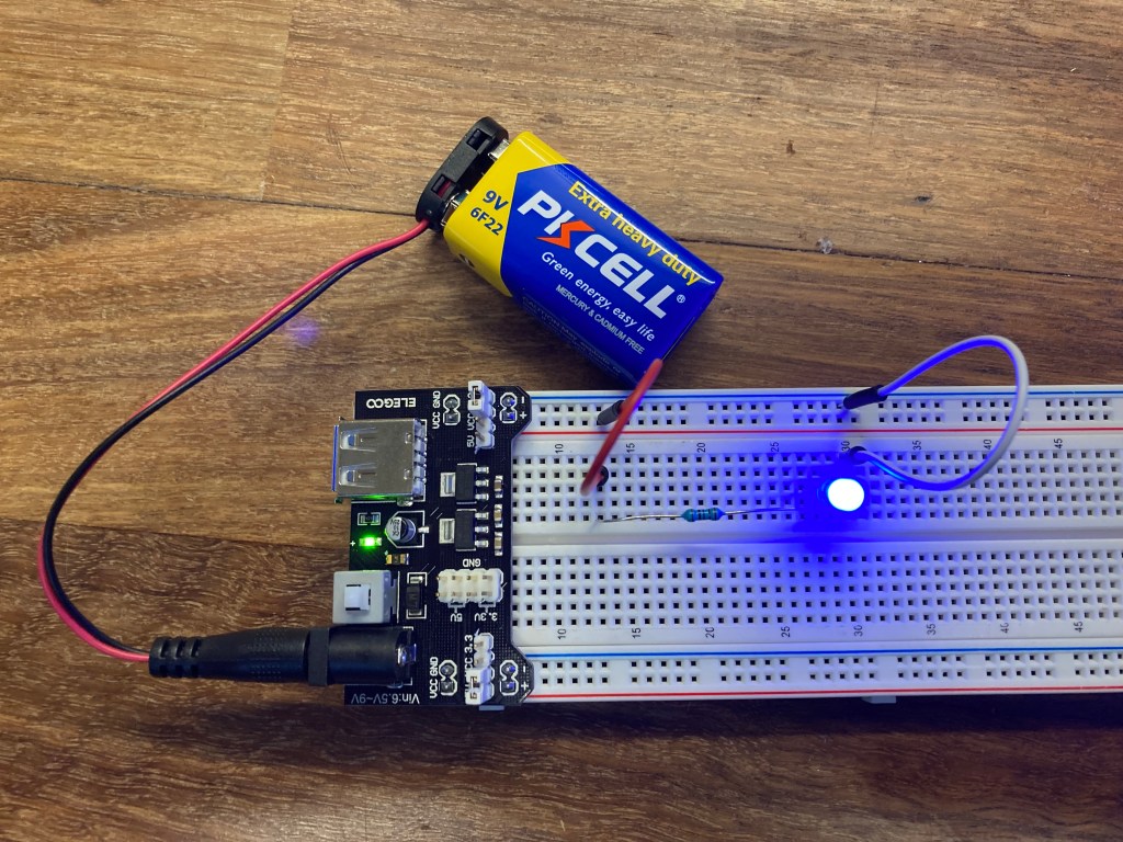
Part 2: 3.3V Power Supply Circuit

For the second part of the lab, I created a simple circuit that powers a blue LED light using the 3.3V power supply side of the Power Module. Since the LED light has a max rating of 0.04 Amps (or 40mA), I assumed the LED would need 30mA of current to power the LED. In order to properly use the LED without overpowering the LED, I used Ohm’s Law to calculate the required resistor to meter the flow of electric current.
Ohm’s Law:
Voltage(V) = Current(I) * Resistance(R)
R = V / I
= 3.3 V / 0.03 A
= 110 Ohm
Since our kit does not have a 110 Ohm resistor, I used a 100 Ohm resistor instead.
3.3V Circuit
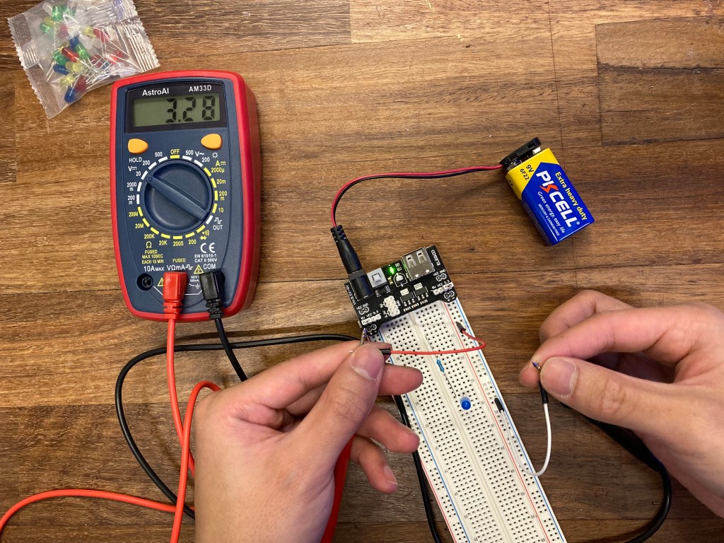
Once the circuit was set up, I used the Multimeter to check the voltage of the power supply. The reading was 3.28 Volts due to the unstable connection between the jumper wires and my fingers holding the wires.
Part 2 continued: 5V Power Supply Circuit
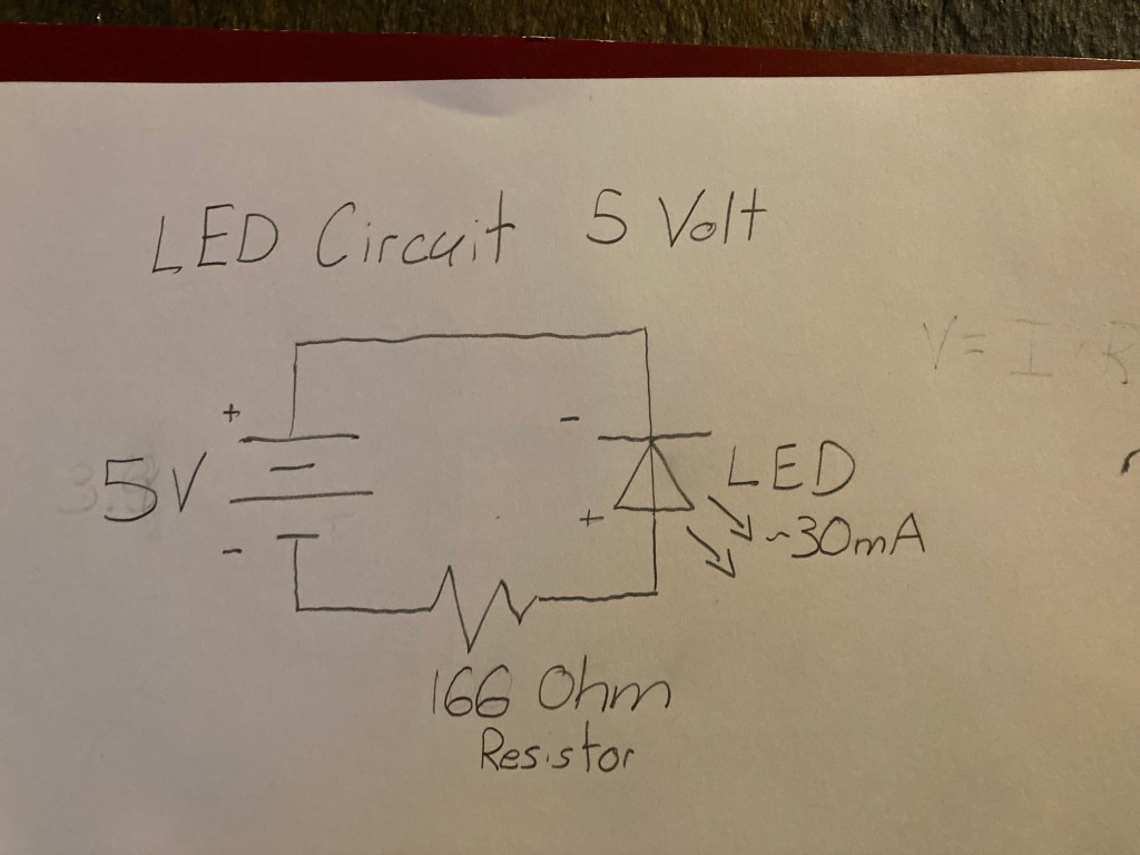
The next part of the lab was to recreate the previous circuit with a 5V power supply instead of 3.3V. The basic setup remained the same, except for e new calculation for the resistance required due to the increase in voltage powering the circuit.
Ohm’s Law:
Voltage(V) = Current(I) * Resistance(R)
R = V / I
= 5.0V / 0.03 A
= ~166 Ohm
Using Ohm’s Law again, the required resistance calculated was 166.66 Ohms. Again, since the kit does not have the specific resistor, a 100 Ohm resistor was used again.
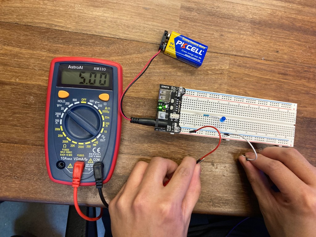
5V Circuit
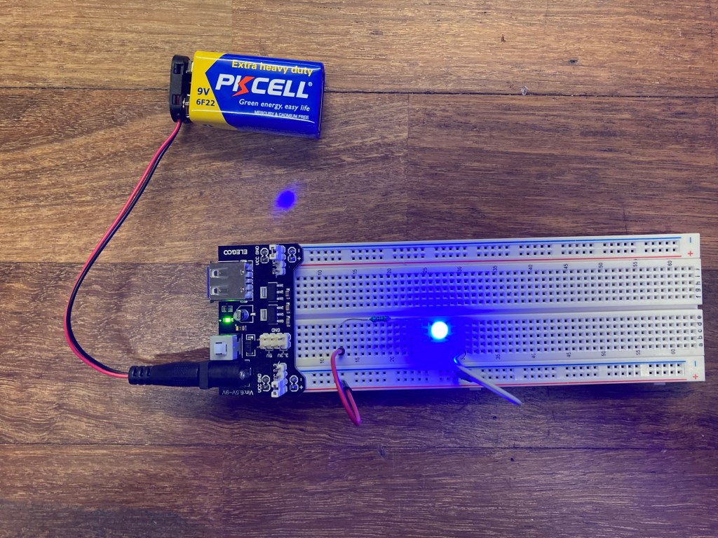
Using the Multimeter again, I measured the voltage of the 5V circuit to ensure the correct power supply was used to power the circuit.
Part 3: Button-ON Switch 5V Power Supply Circuit
The final part of this lab was to incorporate a momentary push button that will power the LED when the button is held down. In order to do so, the button would need to act as a switch that keeps the circuit ‘open’ when the button is idle, and ‘closes’ when the button is pushed and held. The button essentially completes the circuit when the button is pushed and breaks the flow of electricity when the button is left idle.
Button-ON Switch 5V Circuit Diagram:
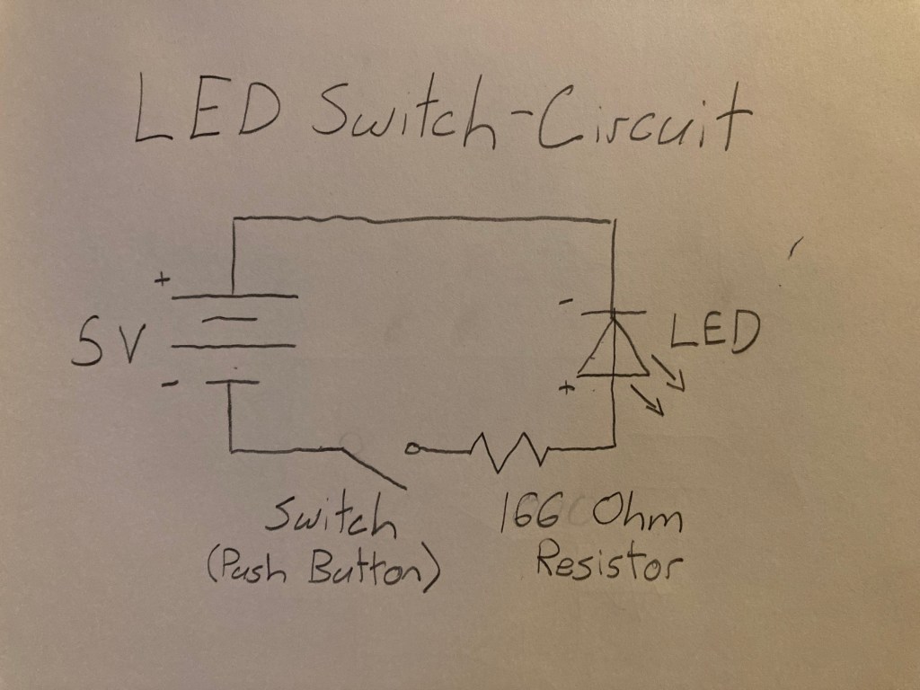
*NOTE: The lab description asked to use the 3.3V setup for the switch, whereas I used a 5V power supply. Since the schematic is essentially the same, this setup should suffice for this part of the lab.
Extra Volt: Button-OFF Switch 3.3V Power Supply Circuit
For the Extra Credit challenge portion of this lab, I created a circuit that does the inverse of the Button-ON switch in Part 3. Now, the button turns OFF the LED when pushed, and activates the LED when not pushed.
Button-OFF Switch 3.3V Circuit Diagram

My thought process behind this circuit was to create path of least resistance when the the button is activated. When the circuit is ‘broken’ while the button is not being pushed, the current should flow through the LED. But when the button is pushed, the current should flow through a different path from LED in order to turn off the LED. By creating a parallel circuit with the button and LED, a junction is created to divert the flow of electricity depending on the state of button. The LED has greater resistance than the button, so the electrons will follow the path of least resistance when the button is activated.
Conclusions:
This lab introduced me to the importance of Ohm’s Law and drawing basic circuit diagrams. I found it easier to create a circuit diagram that resembles a circular flow of electric current that flows from the battery, though the components, and then back to the battery. Once the diagram is correctly drawn, I found it much easier to construct the circuit, especially in the Extra Volt part which required a junction in the circuit to divert the flow of electricity.
